Wing Assembly
Each wing, counting the 27 pieces in each rib consists of over 1,000 pieces of wood. That's a lot of work. In my build I actually made 5 wing panels - the first one I made I was just not happy with the way it came out so it was discarded. In fact, I have had so much rework that I tell people that by the time I finish this plane I will have actually built three of them!
Another point - none of the wings are the same. One lower panel has a wing walk, the other doesn't and the top wing panels are complex because they are longer and have a different aileron attachment as well as different center section openings. Once I got good at making the wings it took about a month to assemble each one.
Ribs and Spars
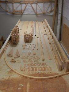
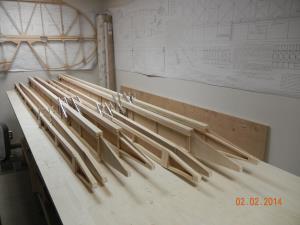
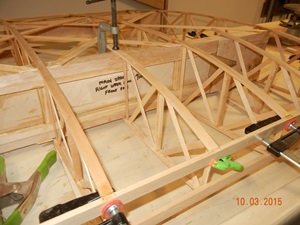
A pattern rib was made from that drawn on the print. From the pattern rib the full set of ribs for the four wing panels were made - making each rib identical in shape. This aircraft requires 46 full size ribs and 38 half (or "false) ribs for a total of 84 ribs. The development of the pattern rib, jig and the ones that will be used on the plane took almost a year to complete. For the record, each rib consists of 27 pieces of wood, no two are the same size and shape!
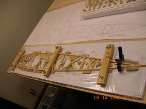
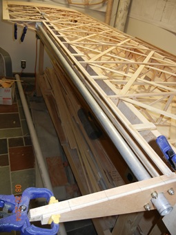
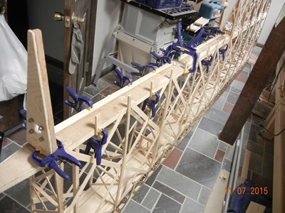
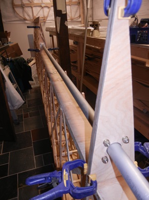
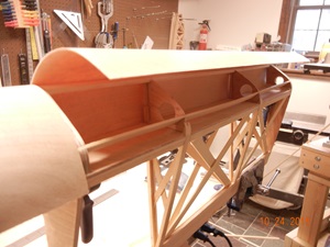
The main spars are a complex I-beam structure consisting of spruce spar caps and 1/8" aircraft grade plywood webbing. In addition to the basic I-beam structure, there are stiffeners located between the spar caps at each rib location and additional structure located where fittings for the wings to fuselage carry thru's and interplane struts attach.
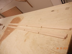
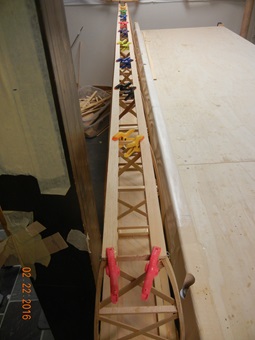
There are also rear spars which are in a "C" shape with 3/4" spruce spar caps with plywood web - but the web is attached to the outside of the spar caps forming the "C" shape, not in the middle like the I-beam shaped main spars. The rear spars also have internal stiffeners at each rib location and additional structure, like the mains, at the attach points.
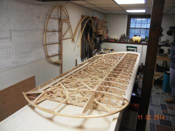
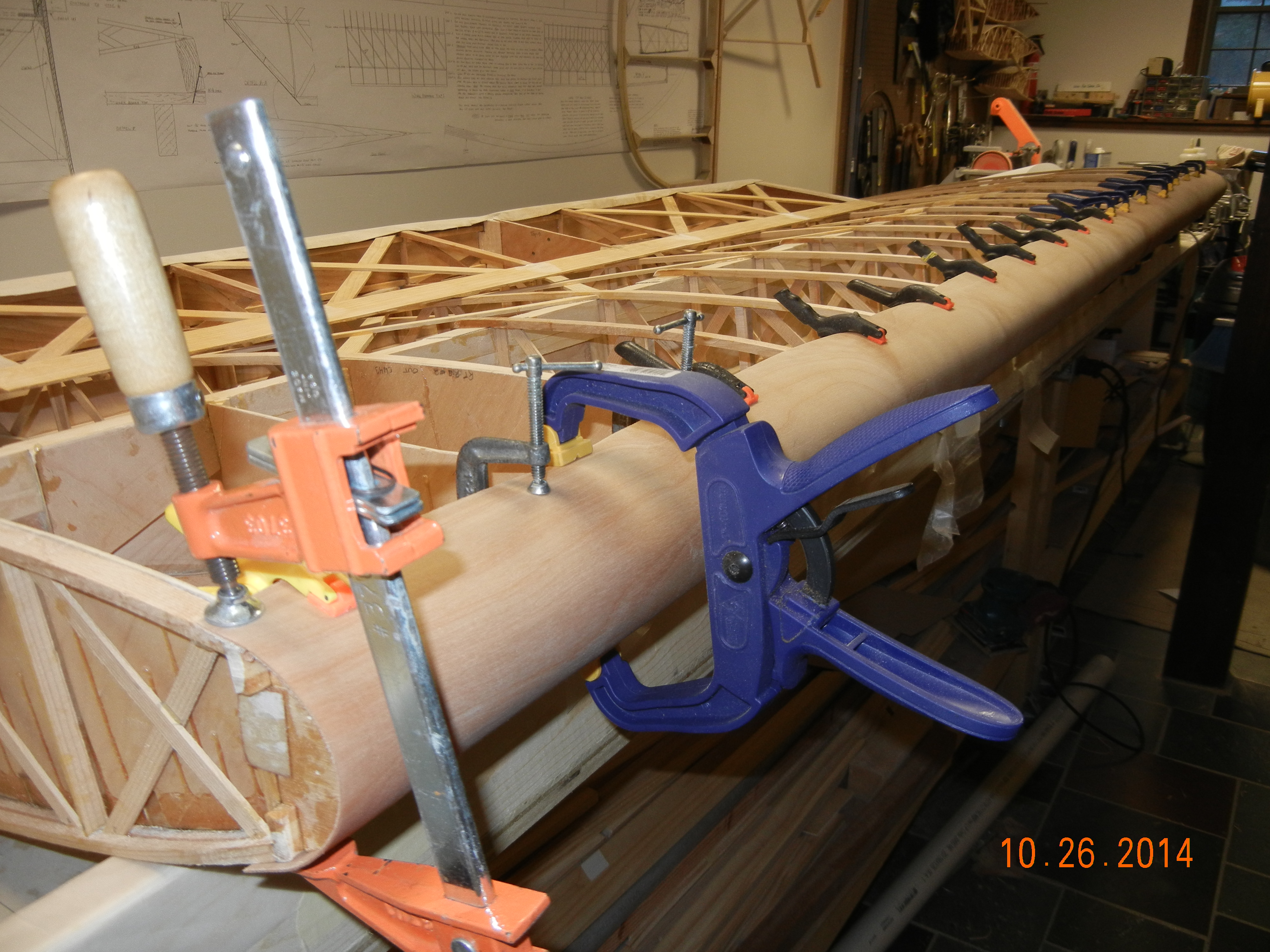
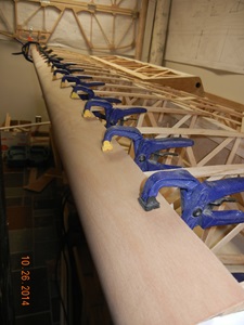
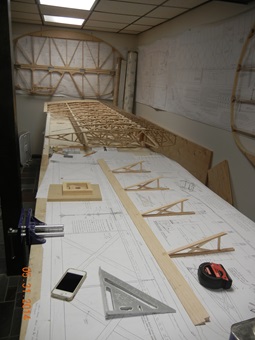
In the picture above on the right you can see the full set of 8 finished spars. From left to right: the first 4 spars are for the the lower wing panels (10 feet long) and the next 4 are for the upper wing panels (11 feet long). The triangular ends are for wingtip bow attachment. Hard to see in the photo is that each pair of spars is constructed as a mirror image of each other to fit on the corresponding wing panel.
Leading and Trailing Edges
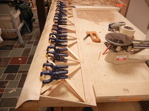
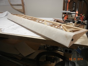
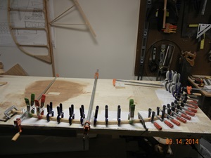
The planform of the ribs is a Clark-Y. There is no flat side so you need a jig to set up the trailing edge. The trailing edge material compensates for some of this as it is a triangular shape that is fabricated from pine or spruce and notched for the rear of each rib to fit. There is also a groove on the inside of the material where geodetics will attach. The jig I constructed is a 2 x 4 with a chamfer cut to the proper angle of the trailing edge material.
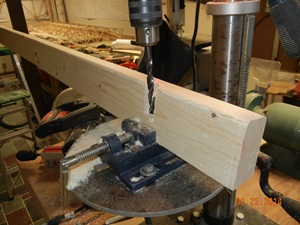
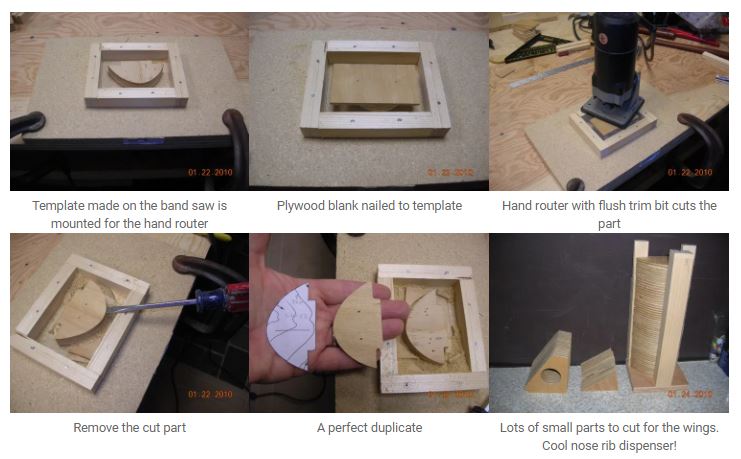
Once the trailing edge is supporting the ribs, the spars can be slid into position and bonded. Then it is time for the leading edge. Each full rib and each false rib has a nose rib. Since these form the shape of the leading edge it is important to have no variation in the shape of each nose block. The illustration below shows how I used a hand router and a flush-trim bit with a template (cut by hand from 3/4" plywood on a band saw) to make all 80-something nose blocks identical.
The first step is to affix false spars to the front of each rib that run the full length of the wing. These spars will support the nose rib blocks which in turn will support the leading edge material.
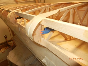
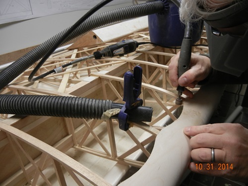
After the nose ribs are all aligned and bonded, 1/32" 3-ply aircraft grade plywood is soaked, curved (I used a length of PVC pipe with water in it), and attached around the nose ribs with each side glued to the upper and lower false spars.
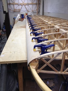
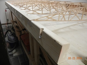
Then scallops are cut into the leading edge, top and bottom, to allow for some flex in the wing. It also looks really old fashioned! I used a Dremel tool with a flexible shaft and a sanding drum to get the shape just right.
Ailerons
The ailerons are probably the most complex part of wing construction. The idea is easy: the aileron is built into the wing and then cut out. You take the section from the wing that will be the aileron bay and put some structure in there to support the movement of the aileron torque tube and the bending moment imposed by the ailerons. Then you add structure to the part that you cut out - a spar, a leading edge, and side structure to support the bearings and torque tube.
Well, it really sounds simple but I found it quite challenging. So much so that I tore up two ailerons that were made and had to rework them!
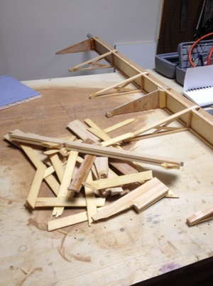
REWORK !!!
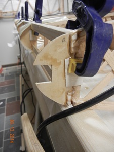
This all starts with cutting the aileron out and making the cavity in the wing that will be the aileron bay. In the leftmost picture below you can see the cut our aileron in the foreground and the wing with the now empty aileron bay in the background. You have to make some sort of jig to ensure that you cut through the ribs in exactly the same spot so they are all even. Then you add structure all around the bay so that it is rigid.
Adding the structure is woodworking. You have to build corner blocks and cut around other structure that is already in place.
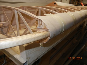
Once the aileron bay is complete, the aileron itself can be constructed. You begin by working with a fairly flimsy structure made up of what remains of about 5 ribs and the trailing edge. To this you fabricate a spar, nose ribs, and a leading edge made from 1/32" plywood that is soaked and bent around the nose rib sections. Then additional stiffeners and side structure to get the thing all rigid. It is complicated, takes quite a while but after doing 4 of them(or like me - 6 of them!) you'll get the hang of it.

It is amazing how, once soaked, the 1/32" plywood molds itself to even sharp curves. A completed aileron is a thing of beauty. Too bad we have to cover it someday.
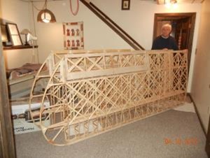
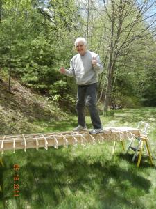
Just to prove to myself that the wing is strong (each completed wing weighs under 50 lbs) I decided to see if it would support me. The first wing that I decided to keep was the lower right. This wing panel has the wing walk structure used to enter the aircraft. It is a complex nest of wood parts and plywood covering. I wanted to see if it would actually support me. So before even finishing the full wing (the leading edge, aileron bay and wing tip bow had not been completed) I took it outside and suspended the root end from the attach fittings to a saw horse and the tip end on another saw horse.
Once I found myself standing on the wing walk, I could not resist finding out if the rest of the wing would support me. So I walked, carefully, out on to it with each foot following a spar. This is no scientific test but knowing that the wing loading of this aircraft should support over 300 lbs per wing in normal 1g flight, I was happy that it at least supported me (at about 2/3 of that).
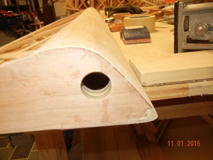
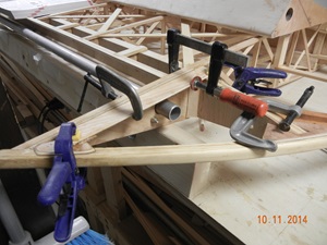
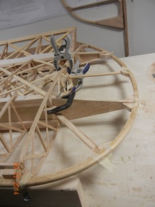
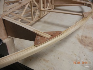
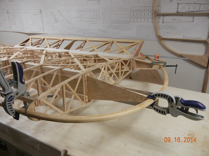
Wing Tip Bows
The wing tip bows are laminated 3/4" x 1/8" strips just like the leading edges of the horizontal stabilizer, fin and the trailing edges of the rudder and elevator. The bow attachments are some of the least well documented parts of the prints for this aircraft. The drawings do not provide many details as to how to actually attach the bows to the rest of the wing structure but it is clear that they have to tuck in under the leading edge of the wing and match up somehow with the trailing edge.
Structure also has to be fabricated where the trailing edge and the wing tip bow meet. This attachment point is also against the outermost part of the aileron bay and requires additional gussets and stiffeners so that when the fabric tightens it does not pull all this out of alignment. Once the attachments to the leading and trailing edges are figured out, the attachments to the wing tip bow supports at the ends of the spars can be figured out. These require careful trimming, corner blocking and gussets. The finished wing tip bow is a real thing of beauty!
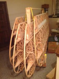
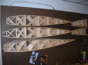
The wings were large enough and awkward to store so I made a rack to hold them.